In metal parts manufacturing, sheet metal cutting is one of the first operations that directly affects the technical compliance of the finished product. The dimensional accuracy, edge quality, geometric stability, and structural condition of the cut part can determine the effectiveness of subsequent machining processes. A cutting deviation that initially seems insignificant can later cause welding, bending, or assembly problems, and in extreme cases, may require remanufacturing the part. In a significant portion of industrial orders, production does not end with cutting the sheet. Parts are bent, welded, machined, their surface treated, and then incorporated into larger structural units. These operations build on each other, so deviations arising in the first machining phase can be reflected throughout the entire manufacturing process. The problem is particularly significant when the cutting technology is selected solely based on material thickness, cutting speed, or the direct cost per part. A process that seems economical can later result in significant post-processing, longer assembly time, or a higher defect rate. Therefore, to select the appropriate sheet metal cutting technology, it is necessary to know the properties of the raw material, the function of the part, the permitted dimensional variations, and the requirements for subsequent manufacturing operations. Laser cutting, plasma cutting, flame cutting, mechanical cutting, and waterjet cutting have different technological characteristics that provide appropriate results under different conditions.
Why can improper cutting technology cause problems?
The conformity of the cut part is determined by several interrelated geometric and material technology properties. In addition to meeting the nominal dimensions, attention must be paid to the perpendicularity of the cut edge, surface roughness, burr formation, flatness, and material structural changes resulting from machining. For example, a sheet metal part may meet the length and width dimensions specified in the drawing, but due to the slope of the cut surface, it does not fit properly with the related structural element. A similar problem can arise if a hole has a nominal diameter but the hole’s axis or position differs from the design. Some cutting defects are directly recognizable. Significant burrs, adhered slag, or visible deformation can be detected after production. Other deviations only appear in the next work phase. These can include unfavorable material structure caused by heat, improper welding edges, or geometric inaccuracies causing problems during later assembly. The risk increases the more operations are involved in the given part. For a simple structural element with high dimensional tolerance, certain surface differences may be acceptable, while for a precision machine part, these can hinder the prescribed operation.
Dimensional inaccuracies and geometric deviations in cut parts
Dimensional accuracy is one of the fundamental requirements in component manufacturing. However, several factors influence the actual geometric dimensions during the cutting process. In thermal cutting, the material melts along the cut gap or is removed through an oxidation process. The resulting cutting gap width depends on the technology used, equipment settings, and raw material properties. If the compensation for the cutting gap is not properly determined, the finished part size may differ from the value shown in the digital design. The defect can be particularly problematic for internal cutouts, holes, and connection surfaces requiring precise joining. An oversized hole can cause uncertainty in the joint position, while an undersized opening may require further machining. In plasma cutting and flame cutting, the perpendicular of the cut surface is also an important issue. The upper and lower widths of the cutting gap can differ, resulting in an angled cut surface. This phenomenon becomes especially significant when two parts must fit properly across their entire cross-section. Modern laser cutting equipment is suitable for creating high-precision contours with proper parameterization. However, the actual result is also influenced here by the machine’s condition, material thickness, cutting speed, and raw material quality. Therefore, dimensional accuracy requirements must be clearly defined already during production preparation. It is especially important to distinguish between general dimensional tolerances and geometric requirements critical for operation.
Deformations caused by heat
During thermal cutting processes, the raw material undergoes significant local heat load. Different thermal expansion of the heated and cooling material parts, as well as the remaining internal stresses, can cause geometric deformation. The degree of deformation is influenced by the quality and thickness of the raw material, the geometry to be cut, and the applied technological parameters combined. Long, narrow sheet metal parts, thin-walled elements, and workpieces containing many closely spaced cutouts can be particularly sensitive. During the cutting process, unfavorable heat distribution can develop in these parts. In practice, deformation can manifest as bending, twisting, or deterioration of the flatness of the sheet. Even relatively small deformation during later bending or assembly can cause significant problems. For example, a larger machine cover may appear suitable after cutting at first glance, but if the flatness of the sheet is not adequate, repeatable positioning during bending may become more difficult. As a result, differences may appear between the dimensions of the finished cover elements. The concentrated energy input of laser cutting can reduce heat-induced deformation in many applications but does not completely eliminate the phenomenon. The cutting sequence, the placement of contours, and proper support of the workpiece remain decisive. Therefore, in preventing deformations, alongside the choice of technology, the professional preparation of the manufacturing program also plays a significant role.
Changes in the heat exposure zone and material structure
When applying thermal cutting technologies, a so-called heat zone can form in the material. This is a region in the immediate vicinity of the cut edge, whose microstructure can change due to heat load. The extent of change depends on the composition of the raw material, the amount of heat input, and the rate of cooling. In some steel grades, rapid heating and cooling can cause local hardness increases, which under certain load conditions may cause unfavorable properties. The heat zone is especially important for components that will later be subjected to welding, bending, or repeated mechanical stress. Therefore, for high-strength steels, special alloys, and heat-treated raw materials, it may be justified to evaluate the cutting technology applied from a material technology perspective. A Laser Cutting generally allows for the formation of a narrower heat zone, than traditional thermal processes with significant heat input. However, actual structural changes in materials may also require investigation in the case of laser cutting. If the complete exclusion of thermal effects is a technical requirement, waterjet cutting can be a suitable alternative. In this process, material removal occurs through mechanical erosion, so the thermal zone characteristic of thermal cutting is not created. Therefore, when selecting the cutting technology, the additional stress on the raw material must also be taken into account, especially if the component functions as part of a safety or heavy-load structure.
Burr formation, slag residues, and inadequate edge quality
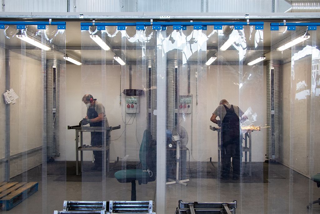
The edge quality developed during the cutting process directly affects further machinability. Burred or slag-contaminated parts often require additional cleaning, grinding, or edge machining operations. During plasma and flame cutting, part of the molten material can solidify at the bottom of the cut edge, forming a slag-like deposit. A similar phenomenon can occur in laser cutting, especially with inadequate cutting parameters, auxiliary gas supply, or poor material quality. The roughness of the cutting surface is also decisive. An uneven, heavily grooved surface can be unfavorable for parts that require precise fitting, proper surface contact, or a defined surface treatment quality. Burr formation can also complicate assembly work. Sharp edges can hinder proper contact of parts, cause injury during assembly, and in certain applications, may cause damage to related seals, wires, or other components. Edge preparation before surface treatment is especially important. A in powder coating, in painting and other coating processes, proper surface cleanliness and edge design fundamentally affect the quality of the coating. Removing remaining burrs or adhered slag requires additional working time and machine capacity. For larger quantities, this extra work can also have a significant impact on the overall profitability of production.
How does cutting quality affect subsequent welding?
In the manufacture of welded metal structures Proper component preparation plays a decisive role in the quality of the joint. The geometric accuracy of the cut elements affects the weld gap, the joint position, and the required seam design. If the size or angle of the connecting surfaces differs from the design, welding preparation can become more complicated. Too large a joint gap may require a larger amount of yield material, modified welding parameters, or special preparation for certain joints. A gap that is too small or uneven can hinder the required root fusion or result in unfavorable joint geometry. Special attention should be paid to the oxide layer and other contaminants formed on the cut surface. In the case of thermal cutting performed with oxygen, an oxide layer may form on the cut surface. The nature and thickness of the layer depend on the technology used and the properties of the raw material. In certain welding processes, an oxidized or contaminated surface can adversely affect bond formation, so proper cleaning and edge preparation are essential.
Problems can especially arise with complex welded structures consisting of multiple components. If the inaccuracies of individual elements accumulate, the overall geometric dimensions of the structure may differ from the design. In such cases, welding devices and fasteners alone cannot correct all deviations. Forced joining of improperly prepared parts can also create additional internal stresses. Accurate cutting is therefore an important prerequisite for welding quality, supporting the reduction of later deformations and the repeatability of production.
What problems can occur during CNC edge bending?
A significant portion of sheet metal parts are shaped to their final shape by bending after cutting. CNC edge bending However, its accuracy is also influenced by the geometric condition of the starting workpiece. During bending, the material undergoes plastic deformation along the defined bending line. The resulting angle and size depend on material quality, sheet thickness, tool geometry, and machine settings. If the size of the cut sheet differs from the prescribed value, the edge length formed after bending may also be faulty. Therefore, the initial length deviation can be directly incorporated into the geometry of the finished part. The problem can be further aggravated by deformation during cutting or deterioration of the sheet’s flatness. Positioning a workpiece that does not fit properly is more difficult, which can also adversely affect the repeatability of the bending site. The placement of holes and cutouts is also important. If an opening is too close to the bending line, it can deform during forming, even if the cut itself was accurate. A significant portion of such problems can already be recognized during design and production-preparation. Therefore, in proper part design, besides cutting accuracy, bending radii, sheet thickness, hole spacing, and the limitations of the applied bending technology must also be taken into account.
When the cutting error is only discovered during assembly
One of the most costly problems in part manufacturing is when a deviation from a previous operation only becomes noticeable at a later stage of the manufacturing process. Not all assembly problems may be discovered during the inspection of a separate sheet metal part. It may happen that the dimensions individually fall within the specified tolerances, but the differences between the connected parts accumulate in an unfavorable direction. This phenomenon is known in manufacturing technology as the tolerance chain problem. For example, in a complex mechanical structure, the holes of several sheet metal parts must be aligned with each other. If a small, identical deviation occurs in every part, inserting screws or other fasteners during assembly can become difficult. Correcting the defect may require post-drilling, part replacement, or partial disassembly of the structure. Mechatronic systems can be particularly sensitive, where mechanical components must cooperate precisely with electrical, pneumatic, or other actuators. Incorrect hole positioning, improper flatness, or inaccurate connection surface can affect the placement of wires, sensors, linear wires, and other structural elements. To prevent such deviations, it is advisable to choose cutting technology already after knowing the entire assembly process.
The quality of the cut edge and the long-term load capacity of the part
The impact of cutting technology can sometimes also occur during the use of the part. The roughness of the cut surface, resulting notches, changes in material structure, and residual stresses can influence the part’s behavior under load. This is especially important for structural elements subjected to repeated or varying mechanical stress. During the fatigue process caused by repeated loads, cracks often originate from geometric or surface stress concentration points. An unfavorably shaped inner corner, notch, or roughly cut surface can increase local stress under certain conditions. The significance of the cut edge condition can therefore go beyond dimensional accuracy and aesthetic appearance. For heavy-load, safety-critical components, it is advisable to define the appropriate edge design, any necessary finishing, and quality control requirements already in the design documentation. During the technological decision, the fatigue properties of the material, the planned load cycles, and the technical specifications applicable to the given structure must be evaluated together.
What differences can the quality of the raw material cause?
The same cutting technology can yield different results for different raw materials.
Carbon steels, stainless steels, aluminum alloys, and special high-strength steels differ in their thermal conductivity, thermal expansion, and material structural properties.
-
- For example, oxygen-assisted laser cutting of carbon steels can provide an effective solution in many applications, but the oxide layer formed on the cut edge may require removal in certain additional operations.
- Nitrogen laser cutting is often used for stainless steels to reduce oxidation on the cut surface. With proper technological adjustment, the process can provide favorable edge quality.
- machining aluminum sheets, special attention must be paid to cutting parameters due to their high thermal conductivity, significant thermal expansion, and the characteristics of the alloy.
- For high-strength or heat-treated steels, the heat effect resulting from the cutting process can cause structural changes in the material, so in certain applications, it is also necessary to consider the material manufacturer’s technological recommendations.
Selecting the raw material and defining the cutting technology is a closely related manufacturing technology task. A solution that provides adequate results for general structural steel may require further testing with special alloys or increased mechanical requirements.
How can cutting errors increase manufacturing costs?
The cost-effectiveness of cutting technology is often evaluated based on machine hour cost and direct cutting time. This is important information but does not provide a complete picture of the cost of producing the part. A cheaper cut part can be more expensive overall if it requires significant deburring, grinding, hole correction, or other post-processing. In addition to the direct labor and machine costs of additional operations, the resource requirements of material handling, in-process storage, and quality control must also be taken into account. If the cutting error is discovered only after welding or bending, the defect value already includes the cost of previous operations. Therefore, a late detection of geometric deviation can cause significantly greater losses than detecting the same defect immediately after cutting. In series production, repeated minor problems can be particularly significant. If every part requires a few minutes of post-processing, the extra time can increase to significant working hours with a larger quantity. This can be combined with reduced production capacity and longer lead times. Therefore, when selecting the technically appropriate cutting process, it is advisable to consider the entire manufacturing path of the part. True cost-effectiveness can be assessed based on the total cost of raw material usage, cutting time, post-processing, quality control, scrap, and related manufacturing operations.
How can cutting errors be prevented already during production preparation?
Selecting the appropriate cutting technology requires detailed technical preparation. The starting point of the process is the precise definition of the functional and geometric requirements of the part. The technical drawing must clearly state the quality of the raw material, nominal thickness, critical dimensions, and required tolerances. In cases justified for later use, requirements regarding edge quality, burr-free status, and the condition of the cut surface must also be recorded. The ISO 9013 standard provides an appropriate framework for defining the quality requirements of thermal cutting processes. The standard deals with the classification of geometric and quality characteristics of flame-, plasma, and laser-cut surfaces. However, the application of the standard does not replace the definition of specific requirements arising from the function of the part. For a structural element requiring precise hole position or special fitting, additional size and geometric specifications may be necessary. Based on the manufacturing documentation, it is advisable to examine the technology with which the given contour can be produced with the required quality. Manufacturability testing can be especially useful for complex components. During this, it can be checked whether the planned geometry, hole placement, narrow material bridges, and subsequent bending lines meet the capabilities of the applied technology. In mass production, producing samples and measuring checks can help finalize technological parameters. A properly prepared manufacturing process can reduce the risk that defects will only become detectable during later assembly or final inspection.
Why is it important to coordinate cutting technology with the entire manufacturing process?
In modern parts manufacturing Cutting, bending, welding, surface treatment, and assembly are closely connected technologically. The machining process can be organized efficiently if the requirements of each operation are considered already during the production plan. For example, when selecting the cutting technology for a bent and welded sheet metal part, it is important to know which surfaces will later become joining surfaces, which holes will serve positioning purposes, and what dimensional accuracy must be ensured during assembly. It may happen that some contours can be formed with adequate accuracy already in a flat state, while other details should be machined to the final size after bending or welding. Such decisions require knowledge of different manufacturing technologies and an understanding of the entire part function. Coordination of operations can help reduce in-process corrections, reduce defects, and ensure repeatable quality.
This is especially important in complex, high-volume parts manufacturing projects, where a single technological problem can affect the performance of multiple consecutive work phases.
How can we help?
Innomechanika Ltd. supports the production of metal industry parts from technical preparation to the production of finished components. Our services include 2D and 3D laser cutting, CNC edge bending, welding, and related machining tasks. During the preparation of manufacturing tasks, we take into account the properties of the raw material, the geometry of the part, the required accuracy, and the requirements of further machining operations. By designing the appropriate technological sequence, we strive to ensure that the cut parts meet technical requirements in the next production phases.
If you are looking for a reliable manufacturing partner for producing custom or mass-produced metal parts, contact our experts. Based on the technical documentation, we help determine the appropriate machining solutions and prepare a quote for the planned manufacturing task.